Week 8 Electronics design
Objectives
Group assignment
Use test equipment in your lab to observe the operation of a microcontroller circuit board
Individual assignment
Use an EDA tool to design a development board to interact, and communicate with an embedded microcontroller, produce it and test it
Group assignment
You can find the group assignment here
Individual assignmnet
Here I’ll try to explain the stuff I had to figure out as spmeone completely new to electronic. First it is important introduce yourself to some basic terms in electronics
Basic units within an electric circuit
Voltage : It is the pressure from an electrical circuit's power source that pushes charged electrons through a conducting loop, enabling them to do work such as illuminating a light.Voltage, also called electromotive force, is simply the energy per unit charge. In other words, voltage is the difference in electric potential between two points.
SI unit: Volt
Current:
Current is just the rate of flow of electric charge. In simple words, the current is the rate at which electric charge flows in a circuit at a particular point
SI unit: Ampere
Power : Electric power measures the rate of electrical energy transfer by an electric circuit per unit of time. Electric power is commonly supplied by electric batteries and produced by electric generators.
Denoted by P and measured using the SI unit of power which is watt or one joule per second.
Basic Electronic components
Types of electronic components; Passive components, Active components
Active components are those components that require energy to work and are able to control the electricity running through them. Typical electronic devices are diodes and transistors, for performing "active" operations such as amplifying, rectifying, or converting supplied current (signal).
Example:
Passive components are components that don't need any electricity to work. They are always on.
Example:
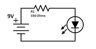
By this time I had learnt that you need a resistor, a power source and an output to create a very simple circuit.
Resistor
The main purpose of resistor is to reduce the current flow and to lower the voltage in any particular portion of the circuit. It is made of copper wires which are coiled around a ceramic rod and the outer part of the resistor is coated with an insulating paint.
The SI unit of resistor is Ohm.
Capacitor
Capacitor , device for storing electrical energy , consisting of two conductors in close proximity and insulated from each other. A simple example of such a storage device is the parallel-plate capacitor.
Diode
A diode is
a semiconductor device that essentially acts as a one-way switch for current
. It allows current to flow easily in one direction, but severely restricts current from flowing in the opposite direction.
Microcontroller
A microcontroller is a small and low-cost microcomputer, which is designed to perform the specific tasks of embedded systems like displaying microwave’s information, receiving remote signals, etc.
The general microcontroller consists of the processor, the memory (RAM, ROM, EPROM), Serial ports, peripherals (timers, counters), etc.
While designing a circuit these are things I learnt in the process
1.Learn basic symbols: This is very important because this will save you lot of time while reading/creating a schematic diagram
2.Understand what function your PCB will be serving
- How to identify the value of the power source
Designing PCB
Installing Kicad
Download the file from here
Adding library
In order to optimise size we use our own library for symbols and footprints in fab. So we download the document from here
.png)
Creating the schematic diagram
.png)
.png)
.png)
Exporting gerber file and converting it to PNG
.png)
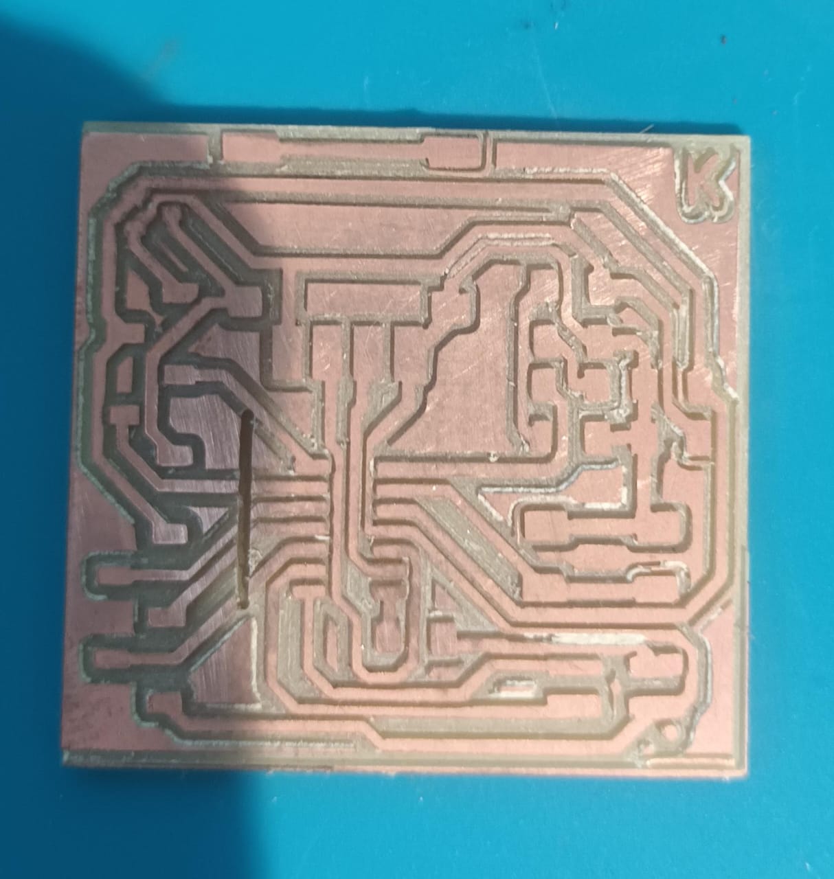
PCB Milling
Once I converted the file in to PNG I uploaded the file to fab mods and milled the pcb using modella
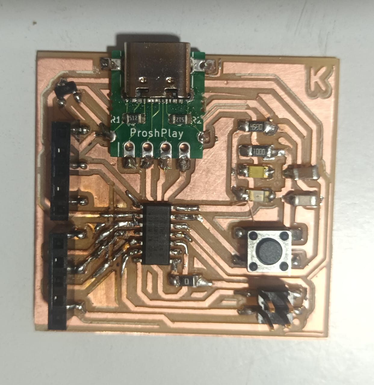
Soldering
After milling I soldered the components on the board